
Purdue Space Program - Liquids
Goals of test
To assess the structural integrity and enhance the performance of the tank transfer line design through static finite element analysis (FEA) of the fuel and oxidation lines under operational conditions.
Why Even Do This In The First Place
This static analysis is essential for identifying peak stress in the Aluminum 6061-T6 transfer line, ensuring structural integrity before advancing to dynamic flight case testing. By optimizing the bending angles and accounting for thermal expansion, we can minimize stress concentrations, prevent failure, and enhance the overall reliability of the system.
Material Justification
We chose Aluminum 6061-T6 for the transfer line due to its superior strength compared to the Aluminum 6063-T6 used for the tanks. Additionally, 6061-T6 offers excellent weldability, ensuring secure and durable joints between components. This material selection provides the necessary structural integrity while maintaining compatibility with the fuel and oxidizer systems.
Source of material property:
Aluminum 6061-T6 - ASM Material Data Sheet
Aluminum 6063-T6 - ASM Material Data Sheet
Failure Prevention
Failure to conduct a proper static analysis could lead to structural failure during flight, causing the transfer line to deform and collapse into the tank. This could result in a complete system failure, jeopardizing mission success and safety. By identifying peak stress locations, we can mitigate potential weak points before moving to dynamic testing.
Boundary Conditions & Load Cases
To simulate real-world constraints, we fixed the transfer line at three support points:
Two supports on the bulkhead of the fuel tank
One support at the end of the oxidizer transfer line
Under operational conditions, we expect thermal expansion to induce slight deformation of the line toward the tanks but without causing buckling. This ensures that the system remains structurally sound during both static and dynamic loads.
Optimization Goals
By refining the bending angles of the transfer line, we can introduce slight controlled deformation that reduces peak stresses without compromising structural integrity. This optimization enhances longevity, minimizes stress concentrations, and ensures that the system can withstand both static and dynamic loads efficiently.
Next Steps: Transition to Dynamic Analysis
This static analysis is a critical first step before advancing to dynamic flight case testing. The insights gained will inform modal analysis, vibration testing, and fatigue life estimation, ensuring the transfer line can endure real-world flight conditions. Addressing these factors early in development prevents failures and refines the overall design for optimal performance.
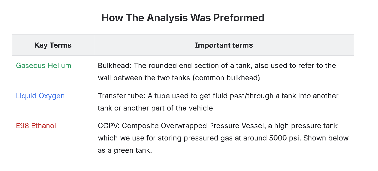
Table
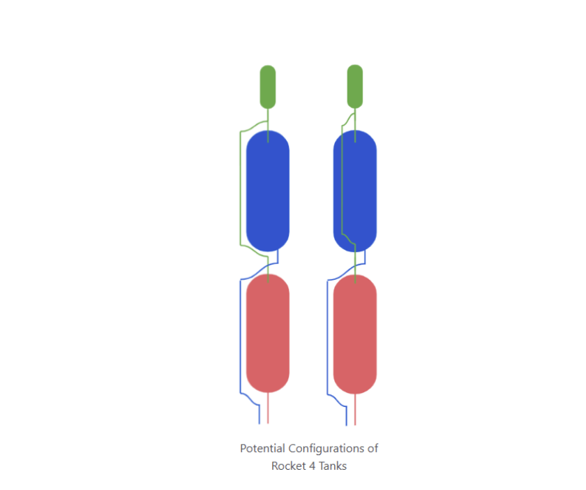
Recipe on for FEA on analysis
Step 1: Preparing the Base
Start by identifying the geometry of the tanks and transfer lines. Create three different configurations to test structural behavior:
Configuration 1: A tank with a 45-degree bend in the helium line.
Configuration 2: A tank with a 50-degree bend in the helium line.
Configuration 3: A design where the helium line passes through the oxidizer tank for an alternative structural layout.
Configuration 4: A fuel system connected to the oxidizer tank, ensuring proper alignment and integration for structural analysis.
Each configuration sets the foundation for evaluating stress distribution and performance under operational conditions.
Step 2: Modeling the Ingredients
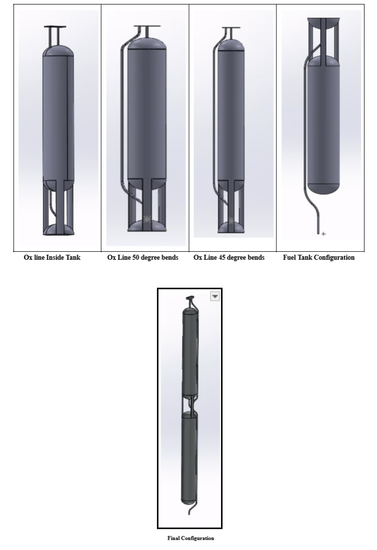
Using CAD software, create four separate configurations of the tank and transfer line system to analyze their structural behavior. Each model represents a unique design variation:
45-degree bend in the helium line
50-degree bend in the helium line
Helium line passing through the oxidizer tank
Fuel system that connects to the Ox bulkhead
To visually represent the final configuration, a CAD rendering was generated to illustrate the design before proceeding to finite element analysis. This ensures a clear understanding of the structural layout and expected stress distribution.
Step 3: Simulating the Heat and Stress
With the CAD models finalized, the next step was to analyze their structural and thermal performance under operational conditions.
All four configurations were imported into ANSYS, where steady-state thermal analysis and steady-state structural analysis were conducted. These simulations allowed us to evaluate how the transfer line and tanks respond to thermal expansion and mechanical stresses.
To ensure accurate results, fixtures and boundary conditions were applied based on real-world constraints. The placement of these supports, as shown in the picture provided below, helped replicate the expected loading conditions and structural behavior of the system. This final step provided critical insights into stress distribution, guiding design refinements before moving on to dynamic flight case analysis.
What were the results
Results – Transfer Line with 45-Degree Bend
The results for this configuration raised some uncertainties, particularly regarding thermal compression. Given that the transfer line is actively being chilled by the oxidizer tank’s temperature, we initially expected some degree of thermal contraction. However, the current results do not fully align with this expectation, so further discussion with the team is needed to confirm the accuracy of the thermal effects.
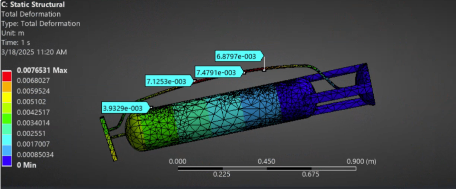
In terms of deformation, the analysis shows minimal displacement along the transfer line. To validate the simulation’s performance, the results were extrapolated by a factor of 5 and analyzed over 2-second intervals, ensuring consistency and reliability.
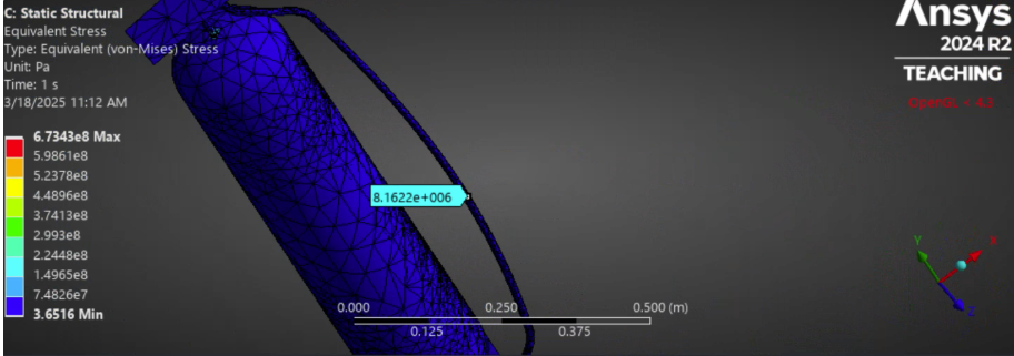
Regarding stress distribution, the maximum stress occurs directly at the midpoint of the transfer line, reaching 8.1622 × 10⁶ Pa. This value remains well below the ultimate tensile strength of Aluminum 6061-T6, meaning the design is structurally sound and ideal for use in the system without risk of material failure under expected loading conditions.
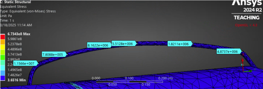
Video for 45 degree analysis: https://drive.google.com/drive/folders/1YXCFql7X2j_jmOYQDr6_rmalvxH0Sf96?dmr=1&ec=wgc-drive-globalnav-gotoYour team sees richer Google previews
Results – Transfer Line with 50-Degree Bend
Currently, there are difficulties in conducting the simulation for this configuration due to errors in the program. These issues are preventing accurate analysis of the structural and thermal behavior of the transfer line.
Once the errors are resolved, the results will be updated to reflect the stress distribution, deformation, and thermal effects for this configuration. Further troubleshooting and validation are underway to ensure the simulation accurately represents real-world conditions.
Video for 50 degree analysis:https://drive.google.com/drive/folders/1ES-J1ltuNk54dfTQncMd7zsyP8XLVfWE?dmr=1&ec=wgc-drive-globalnav-gotoYour team sees richer Google previews
Results – Transfer Line inside Ox tank
This configuration has revealed significant design issues, particularly with high-pressure concentrations at the attachments of the helium line and the fuel bulkhead. These stress points could pose a structural risk under operational conditions.
Results – Transfer Line inside Ox tank This configuration has revealed significant design issues, particularly with high-pressure concentrations at the attachments of the helium line and the fuel bulkhead. These stress points could pose a structural risk under operational conditions.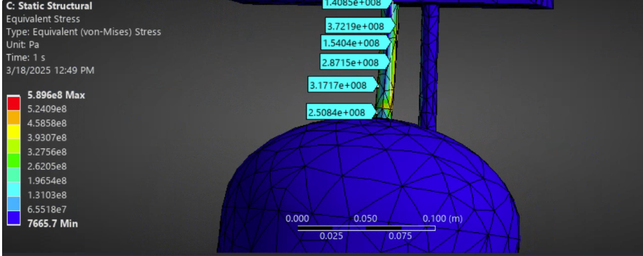
Additionally, during the 2-second static structural simulation, the model exhibited collapse around the oxidizer line, indicating a critical failure mode. This suggests that the current design may not withstand expected loads and thermal effects without modifications.
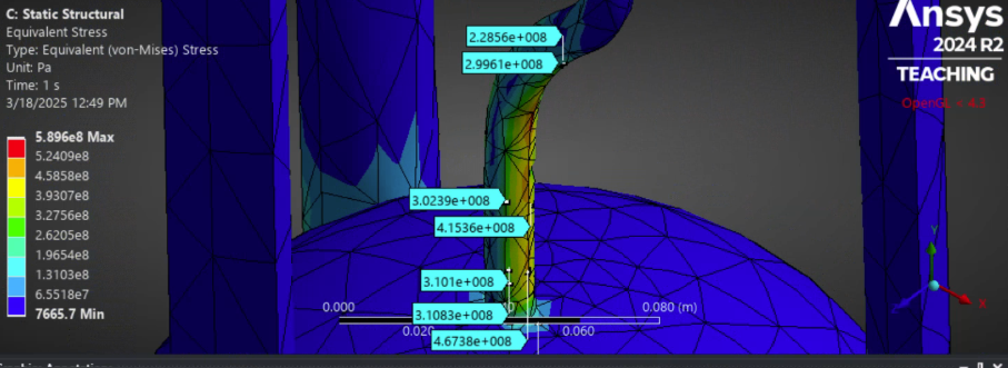
Further investigation is required to fully understand these issues. More details will be confirmed during the PTD (Preliminary Technical Design) review, and this page will be updated with revised results once additional analysis is completed
Video for Inside transfer line:https://drive.google.com/drive/folders/1jegd3QiZuPOnN0xtJbaYznxsL_K9_jiJ?dmr=1&ec=wgc-drive-globalnav-gotoYour team sees richer Google previews
Results – Fuel lineThis configuration appears to be optimal, showing great thermal contraction of the fuel transfer line due to the low temperature of the oxidizer line, which is set to -185.15°C to simulate the presence of liquid oxygen (LOX). The expected thermal compression is evident, confirming the structural response to cryogenic conditions.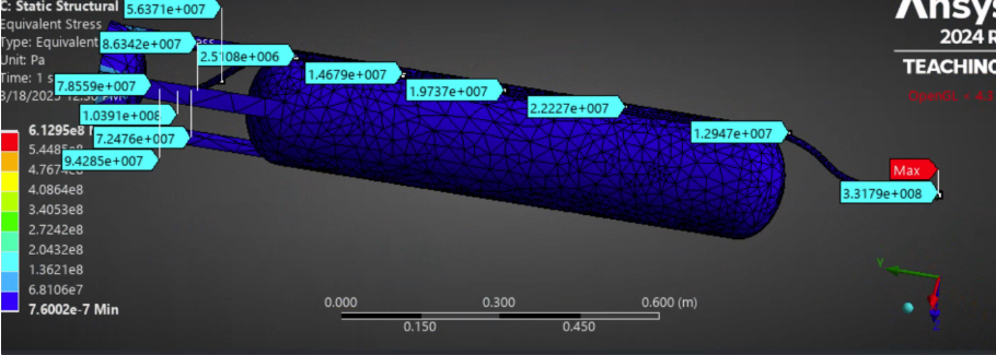
In terms of stress distribution, the maximum stress is 1.0391 × 10⁸ Pa, concentrated at the bottom of the transfer line. While the system remains within structural limits, further efforts can be made to reduce pressure concentrations, potentially through geometry adjustments or support modifications to enhance durability and performance.
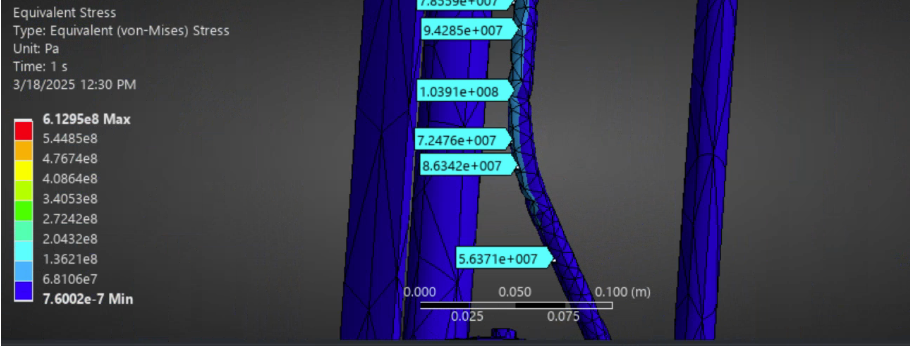
Video for fuel line: https://drive.google.com/drive/folders/1B8ZErk5k27dFTIjz_UNjdywxeFFPgM1l?dmr=1&ec=wgc-drive-globalnav-gotoYour team sees richer Google previews
Core principle learnedThe difference between testing and fucking around is writing down the results ResourcesHere is the Google Drive that contains all of my resources. Go crazy is you want to. https://drive.google.com/drive/folders/1gggfh4aptlGvp1C6GBhtPLzYPC9vUpjD?dmr=1&ec=wgc-drive-globalnav-gotoYour team sees richer Google previewsFurther Improvements To ensure the accuracy and reliability of our findings, the next step is to review the results with the team lead and discuss key observations. A second round of testing will be conducted across all models to confirm that the results remain consistent under identical conditions. Notes Plan on refining mesh a lot better after we pick design of final configurationWill update page once I fix 50-degree simulationAssumptions With Euler Static Equation
